Section 3.1
Steering Beams
Often there are optics in a system that define an optical axis, for example the center of curvature of two mirrors defines the optical axis of a Fabry-Perot cavity. The beam from the laser can be made to propagate along this axis by using a minimum of 2 mirrors. By adjusting the orientation of the first mirror, the position of the beam at the second mirror’s location can be set. By adjusting the orientation of the second mirror the angle of the beam leaving the second mirror can be set. Together this control of the position and angle of the output beam allows it to be adjusted to match to an arbitrary axis.


Section 3.2
Collimating a beam
A common misperception of laser propagation is that laser beams are like pencils of light that travel in a uniform, unchanging beam. In reality most lasers are better modeled as Gaussian beams that have a varying irradiance profile, and a size that expands as it propagates out from the waist (the point where the beam size is a minimum). The rate at which the beam expands as it travels is inversely proportional to the size of the beam waist. A beam focused to a small spot size will diverge rapidly as it propagates away from the spot.
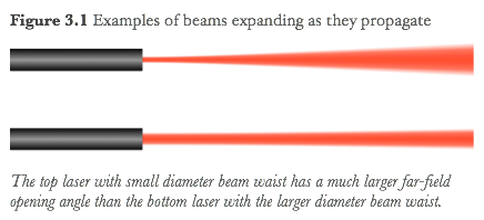
It is often desirable to have a large waist so that the divergence of the beam is negligible and the beam shape can be considered independent of position. This is called “collimating” the beam. This can be achieved by placing a lens one focal length away from the beam waist. For some purposes it is enough to adjust the position of the lens while observing the size of the output beam on a distant target. When the beam is collimated the spot size at a distant point will closely match that at the lens. In practice if you adjust the lens until this condition is achieved you must also check that the spot size in between these two points is comparable in size to know that the light is collimated (it could for example be focused to a waist in between). Often it is adequate to adjust the position of the lens near the nominal position one focal length from the beam waist while monitoring the output spot on a distant wall until that spot size is minimized - this results in a beam that is close to collimated, and often any difference from a perfectly collimated beam is negligible given the accuracy of the method.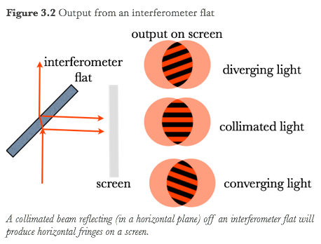
When higher accuracy is required, for instance when the wavefronts are being examined interferometrically and need to be flat, this coarse adjustment procedure is not sufficient. Rather the collimating lens should be mounted on a translation stage for fine control of its longitudinal position (i.e. its position along the beam) while the output is projected on a screen after reflecting off of an interferometer flat - an interferometric device that produces an interference pattern with features that depends on whether the beam is converging, collimated or diverging.
Section 3.3
Working with Infrared or Ultraviolet light
Working with infrared or ultraviolet light presents a challenge in that the light is not visible, so alignment of the optics is less straightforward. In the near infrared between about 700nm and 1.4 μm, an additional issue is that the laser is still able to be focused by the lens in your eye, making it extremely hazardous if you are not wearing safety goggles.
One way to visualize the beam is to combine the invisible beam with a visible beam (using a diffraction grating, or dichroic mirror), and then do the alignment with the visible beam. This doesn’t work so well if there are many optics that need to be aligned that behave differently towards the visible and IR or UV beams, and of course it requires careful alignment of the two beams in the first place.
More direct methods to visualize the beams are shown in the video and include using a camera or a visualizing card.
Section 3.4
Retroreflecting Light
It’s often necessary to reflect a beam back along the path on which it came. For instance in a Michelson interferometer the beams must return to the beamsplitter so that they can interfere. It’s often better to also mode match the input beam and the retroreflected beam , so that the return beam has the same spot size at any particular location as the input beam. This will allow it to retrace its path through the optics experiment without any additional losses due to clipping, and ensures that if multiple retroreflected beams interfere with each other (such as in a Michelson interferometer) the modes will match and produce coarse fringes that can be easily observed.
Section 3.5
A Pinhole for Spatial Filtering
The output of many lasers exhibit speckle that degrades any measurement that relies on a uniform wavefront. When a beam is focused by a lens, the speckle or other high spatial frequency noise makes the focused spot bigger than it otherwise would be. By placing a pinhole or single mode fiber at the focus of the lens to limit the diameter of the spot that can transmit through, this spatial noise can essentially be scraped off the beam - a process known as spatial filtering (other methods such as transmitting through a cavity can also be used).
A common way to “clean up” a noisy wavefront is to use a combination of a microscope lens and a pinhole that is from 5-100 microns in diameter. Special mounts exist to hold the pinhole near the focus of the lens, and to adjust its position along three axes so that the pinhole can be centered on the focused spot.
Spatial filters are particularly helpful in experiments where the the spatial variation of the wavefront intensity is being investigated, such as the Twyman-Green interferometer, or for the creation or reconstruction of holograms.
Section 3.6
Coupling to a Single Mode Fiber
Like the pinhole, a single mode fiber can be used to transmit a single spatial mode of light, providing a clean wavefront at its output. Optical fibers are also useful for bringing light to or from remote locations (such as a rack mounted instrument).
Bare fibers (without a plastic jacket or connectorized end) can be fixed to a mount with a drop of wax one centimeter or so from the end, and the mount can be placed on a 3-axis translation stage to precisely position the end of the fiber at the focused spot of a beam after a lens.
An easy way to couple light into a connectorized fiber is to use a fiber coupling lens which is simply a lens mounted on a fiber connector and positioned one focal length from the plane of the end of the fiber. This can be placed in a kinematic mirror mount, so that when a beam is passing through the center of the lens, tilting the mount causes the position of the fiber end to translate (through the rotation to translational coupling that occurs because the fiber is offset from the rotation point of the mount). In this manner the fiber can be swept through two dimensions while the spot remains fixed. Functionally comparable to a 2-axis translational mount, this is typically less expensive.
Section 3.7
Mode Matching
When interfering two or more beams in an interferometer or cavity, the spatial mode of the beams must match (i.e the spot size and radius of curvature of the wavefronts) to get a uniform interference condition. In a cavity, the mirror spacing and radii of curvature, determine an eigenmode that can propagate around the cavity and return with the same spot size and radius of curvature. To efficiently couple light from a laser into the cavity, the laser mode must closely match this eigenmode. Knowing the Gaussian beam parameters of the laser, one can calculate the position of a lens or pair of lenses that will transform the beam into the desired mode.
Section 3.8
Aligning an Extended Cavity Diode Laser (ECDL)
Laser diodes can be made tunable via frequency selective feedback into the laser diode cavity. In practice this is often provided by diffraction from a grating. Aligning this diffraction grating can be quite challenging because the diffracted spot must couple back into the active region of the laser diode, which is only a few microns wide. Further, the gratings are often physically close to the laser diode so that it isn’t possible to insert a visualizer card to aid in retroreflecting the beam from the grating.
There are a few tricks to aid in the alignment. When the grating is retroreflecting light back into the laser diode, it will also retroreflect light from outside the laser cavity directed towards the laser diode. This means the alignment can be done external to the cavity where there is more space. Also, the feedback from the grating lowers the threshold current for the laser diode when it is feeding back into the active region, thus we can monitor the laser diode threshold current as a means to detect when feedback is present.