Section 2.1
Tools of the Trade
Optical measurements are capable to measuring fantastically small effects. This means, however, that they are also extremely sensitive to unwanted environmental noise. One way that external noise is suppressed is for all of the optics to be firmly mounted onto a sturdy rigid surface so that vibrations and other differential motion is reduced. Thick granite or steel table tops work well in this regard. Most modern optical tables have a steel top with a thick honeycomb-like structure underneath to provide increased stiffness. Air bladders in the legs can be used to “float” the table providing some isolation from ground vibrations (such as those caused by footsteps in the room, mechanical motion of HVAC systems, etc). A grid of tapped holes on the table allow optical mounts to be rigidly secured to the table. Most tables will have 1/4-20 tapped holes on a 1” spaced grid (or M6 holes on a 25 mm grid).
The optical mounts that connect to the table are themselves built of components screwed together with mostly #8 or #6 screws (M6 and M4 for metric units), and #4 (or M3) set screws to hold the actual optics into the mounts. These screws typically require a hex key. While it is quite useful to have a full set of hex-keys available, particularly in a single unit so that the one you need is always accessible, the most often used is the 3/16” (5mm for metric screws) wrench for mounting optics to the table. Although a standard hex-key will work for this purpose, a ball driver, which has the end of the key rounded off so that the driver can be inserted at a range of angles, makes it much easier and is the one tool that you should always have handy when working in the lab.

Section 2.2
Mounting Optics
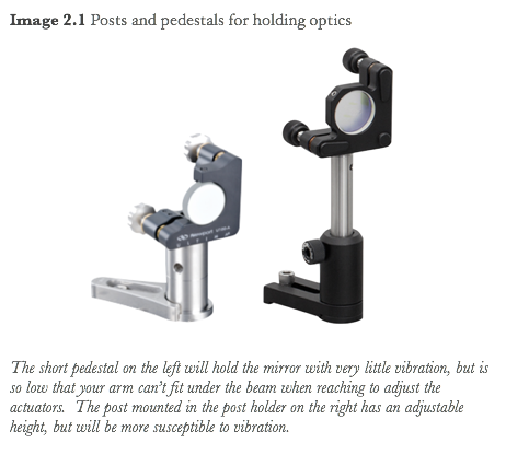
Lots of different mounts are available for laser optics. When choosing a mount what are the things you should consider? Shorter stubbier mounts tend to be more stable (i.e. vibrate less) than taller thinner posts. The flexibility of the baseplate to be positioned to a hole on the optical table independently of the positioning of the optic is a helpful feature. Some mounts hold the optic in a fixed orientation, while others allow tip-tilt control or tip-tilt-translate control of the optic.
Gallery 2.1 Common types of mirror mounts
It can be enlightening to browse through a manufacturer’s catalog of optical mounts to get a sense of what is available and what features differentiate the mounts (for example see Thorlab’s or Newport’s web pages). Regardless of which mount you need for your optics, you will need to mount the optic in the mounting hardware without getting fingerprints on it or cracking it from an overtightened mechanical constraint.

Section 2.3
Beam Height
It’s usually easiest to build an experiment if all of the posts and post holders are set to the same height and the beam is maintained a constant height off the table. Short posts help keep the optics stable so that vibrations are minimized, but if the beam is so low that your hand and arm can’t fit underneath the beam to access things on the table, it will be hard to work with. A 4” (10 cm) beam height is a nice compromise between these two issues.
You may find yourself further constrained by the mounts you have available. Once you’ve selected a desired beam height, you can use a pair of mirrors to steer the output of the laser to be horizontal at the desired height, and you can test and adjust each steering mirror so that its surface is vertical. Once you’ve done this then it is easy to keep the beam at the desired height, and the challenge of aligning optics is greatly simplified since there is only one remaining alignment degree of freedom for the beam.


Section 2.4
Electrically Controllable Mirror
Some applications such as scanning cavities require mirror position and orientation to be electrically controlled. The screw actuators that are used in kinematic mirror mounts can be replaced with actuators that contain integrated piezo-electric elements such as PZTs that can fine tune their length. An alternative solution (that is a fraction of the cost) is to place a bare piezo stacks in series with the actuator between the end of the screw and the mirror mounting plate it pushes against. Multi-layer piezo stacks can be used that require far less voltage (tens of volts instead of hundreds of volts), or when bandwidth is a priority, a small thin mirror can be glued directly onto a piezo.
 By moving just the mass of the mirror (rather than the whole mount) the piezo can respond at frequencies closer to its unloaded resonant frequency. The video shows a third method, of sandwiching a piezo and mirror together for longitudinal position control of the mirror. This geometry is less permanent than the glued mirror and is a useful way to add electronic control to the position of an arbitrary mirror. When working with piezos, remember that polarity matters (only a positive voltage should be applied) so you may need to add a bias to the signal you use to control the mirror. Stacked actuators typically require about 100 V to achieve a few wavelengths of expansion, compared to 1kV or so for standard piezo-electric devices
Section 2.5
Identifying your Optics
It is important to keep optics labeled and well organized when being stored, because it is usually not possible to tell just by looking what the parameters of a lens or mirror are. With narrow band laser line coatings, mirrors may not look reflective to the eye, and at infrared wavelengths materials used for lenses and windows may be opaque to visible light! Nevertheless, there are a few tricks you can use to figure out what an optic is if it is not labeled.
Dielectric coatings are used for controlling the reflectivity of surfaces, and you can identify these coatings by the iridescent sheen they have when viewed at an angle. If only one surface of an optic has this sheen, that is likely the side that is
 to be illuminated. Partially transmissive mirrors (or plate beamsplitters) will have a highly reflective (HR) coating on one surface and an anti-reflection (AR) coating on the other - the HR surface is usually denoted by an arrow or caret mark (^) drawn in pencil on the barrel of the optic pointing towards the reflective surface.
Many optics will have a model number printed or engraved on the barrel of the optic. If you know the manufacturer you can look up the specs for the optic. You might also be able to identify the optics parameters such as wavelength, radius of curvature or reflectivity that are embedded in the part number. For example a mirror made by CVI with part number PR1-1064-90-0537-0.050CC is a partial reflector (PR), optimized for 1064 nm light, with 90% reflectivity. The substrate is 0.5” in diameter and 0.37” thick with 50mm concave (CC) radius of curvature.

If all else fails, you can measure the parameters of your optic using the laser wavelength you intend on using it with. Measure its transmission, reflectivity, curvature or focal length, and effect on polarization.
If you aren’t able to identify your optic, don’t use it in your experiment - many an experiment have misbehaved because someone assumed an optic did one thing when it really did another. These problems can be very time consuming to track down, so it is best to avoid them altogether.
Section 2.6
Laser Camera
Beams can be viewed visually on screens or white pieces of paper, but often it is useful to image the beam using a camera. While it is possible to focus a camera onto the screen being illuminated by the beam, it works much better to directly illuminate the imaging sensor with the laser. This requires removing the lens from the camera. This is particularly helpful when working with near infra-red beams, as they aren’t otherwise visible. While dedicated laser cameras are available, they are quite expensive compared to consumer level cameras. They usually offer the user more direct control over the hardware, such as setting the integration time and the exposure, however, for most purposes a cheap consumer level webcam issufficient. It is usually a simple procedure to remove the lens and infrared filter to expose the imaging sensor.
